
Repairing Elegoo Mars 2 Pro and similar 3d resin printers: The motor is locked up? The printing plate won’t raise or lower? Well this is probably what happened: If you’ve left your 3d resin printer sitting for a while or if it’s cold in the area you’ve stored it you may not be able to get the printing head/printing plate or the arm to which it is attached to raise or lower anymore. You may hear a light thudding or clicking noise as you try to move it with the electronic controls as though the motor is trying to work but nothing is happening. If the motor is making a noise that’s good news because it hasn’t burned out. If it has burned out you’ll need to replace it of course, but if you do hear a noise when you try to move the print head up or down the motor is just seized up. It should be easy to fix. Just turn off the machine entirely with the switch in the back and unplug it to be certain there is no power running to the machine. This will cut the power to the motor so it can be rotated manually. If you haven’t done so already remove the UV blocking protective cover from the machine so that you can access the threaded rod that the print arm moves up and down on. Now using a soft lint free cloth and light pressure rotate the threaded rod manually a bit between your fingertips. Be careful to not tweak or bend the rod. Just rotate it a bit either direction (obviously if you are already at the very top or bottom of the threaded rod you’ll have to go the opposite way) until you hear the motor lightly click once or twice freeing the bearings. Now you can rotate it the opposite way now just to make sure it’s really been freed and try plugging it back in and turning the switch back on. Now try to move the motor using the electronic controls as usual. Hopefully the motor is free now.
Adding a Glass Plate to Your FDM printer.
Measure the thickness of the glass and add about .1 to .2 mm. This is the z offset you’ll need. Before placing the glass bed level like normal on the bed you had and re-home your printer and disable stepper motors. If using a magnetic bed remove top surface and place the glass onto the surface that lies beneath or if using a permanent sticker or the aluminum bed just place the glass on top of that. Hold glass in place with two binder clips. You can use these clips to adjust for some unevenness in the bed if you put them on the parts of the bed that are naturally higher to press those down and so the lower areas free-float higher in relation. Now in Cura go the marketplace and download the z offset setting plugin. Restart cura and under build plate adhesion there will be a new setting called Z Offset. If not visible change the visibility for that setting so you can find it. Set this number to the thickness of your glass plate with that added .1 or .2 mm. Mine is 2.2mm in total. It’s a positive number and you’ll use that same positive number in cura. This is your starting number and you can adjust after a test print. Now update your profile settings to make that change permanent so you never change it back accidentally or you’ll crash into the glass and may crack it or break the hot end off while it’s hot. If something like that happens hit the power switch fast of course, but that should do it for you. If you try to print and the extruder clicks, pause the print, rehome, and then increase that number by about .2 and reslice, reload the gcode and try again, adjust by .1 up or down as needed. If the part doesn’t stick you need to decrease that number by .1 at a time until you find the optimal to get the part to stick with just the slightest amount of glue stick which gives the plate a little texture. Glass is heavier than a normal bed so you can’t run fast or you’ll get ghosting or even layer shifting and it will compress the springs more over time and so you’ll have to adjust that number down by .1 or .05 every so often but the advantage of a glass bed is the flatness of the bottom layer which is important when making machine parts. If your part is stuck to the glass bed turn off the machine and unplug it and wait for it to cool, squirt a little water around the edge and let it soak into the glue and soften it and gently tap the part sideways near the base at the thickest part with the HANDLE of your scraper on all sides and it will pop free. If not wipe up the glue with a paper towel and add more water. If you can lift a corner to help some of the water get underneath or in the center of the part that’ll help too. Just be patient. The glass will break if you aren’t. Remember don’t use too much glue, just enough to very slightly frost the glass. If you are leveled properly and your z offset is set correctly you’ll be good. Some 3d printer firmware allows for a permanent setting for z offset. Mine doesn’t. Supposedly pronterface has a setting for z offset, but it’s never worked for me. I think it uses an older gcode command to adjust for z offset that is incompatible with some printers or it’s simply that my printer doesn’t allow for it and I think the negative and positive adjustment is reversed on there anyway which might be confusing. So I just make my z offset in cura, my favorite slicer.
Repairing 3d Printer Hot-End and tuning up your Anet.
When I first bought my Anet E12 it had a lot of problems and this article is an attempt to explain what I did to get it running as it should.
The package came in good condition, all the parts were there and nothing was bent, so the packers and shippers did a good job. No complaints there.
The bed moves around freely when you first get the machine so it might be a good idea to block it’s movement in some way before trying to get it out of the box and during assembly.
A little about the printing surface: The kit for this printer comes with a sticker to place on the bed as a printing surface. It works just fine, but it’s really hard to remove and eventually you’ll need to replace it. So instead of using the sticker backed print surface I recommend using paper clip type folding clamps to hold it in place initially since removing the sticker is almost impossible even with strong chemicals. The glue is VERY strong and removing it risks bending the bed.
What I eventually did was got a magnetic bed type sticker surface. It has two parts; a sticker for the bottom and a magnetic top that acts like a mat on which you print. You just place the mat on top and print your model and you can remove the mat after you are done and bend it back a little to separate the model from the mat. It basically works, but there was a problem.
Later when I started printing regularly I learned the carriage for the print head was loose and after the hot tip buried itself into the top of the expensive magnetic print surface it was ruined. It’s not very heat resistant. But I did like it so I decided to buy another one but I made one change.
I left the top part off and instead I placed a piece of boro-silicate glass over the sticker surface instead. See I prefer printing on glass for a lot of reasons including it’s heat resistance, but having the sticker from the magnetic surface kit underneath left my option open for using a removable magnetic surface if I ever wanted to.
So I just left the top of the magnetic surface off because it would be too thick otherwise and because the glass would be easier to level without it and because if the magnetic top is heated and cools a lot it will begin to loose it’s magnetism.
While it’s difficult to remove the glass from the sticker surface because it wants to bind with it from the heat it can be done with a spatula wedging it near each of the corners a bit at a time trying not to break the glass. Patience will get it done eventually though. I later fixed the loose printing carriage as you’ll see.
But back to the initial assembly: When attaching the upper vertical rails to the horizontal rails I ran into some trouble because the screw hole on one side was cut a bit roughly and some debris was still in the hole. I cleaned that up by scraping and everything else went together just fine.
Now I just followed the instructions and I was able to get it to do a test print of a chinese chess piece which was a model included on the flash card included with the kit and so I knew the printer worked, but I ran into print problems not long after I really started using the printer. The worst problem was dealing with the hot end so I’ll explain that first.
I ran into some trouble repairing the Anet E12 3d printer because a lot of the parts now available are not what was used for the hot end they put on there. I suspect others will come across the same problems with the same model and other printers by other manufacturers and so I’ll explain the problems I had and how best others should go about fixing them.
The trouble started with the heat-sink which was of the older flat kind instead of the newer cylindrical kind. The grub screw which holds the throat (the hollow cylinder through which the filament flows down into the tip and which is surrounded by the heat-sink) in place stripped out and so I decided to replace the heat-sink thinking that would be the easiest way to repair the printer, but I was quite wrong as you’ll see.
I had also considered drilling and re-tapping the grub-screw hole for a screw that was slightly bigger, but I decided not to since I didn’t have any taps of that size and there wasn’t much space left to do that on the heat-sink.
I considered flipping the heat-sink over and drilling and tapping the reverse side, but again I didn’t have a tap of the required size and I figured replacing the heat-sink altogether would be the most direct way to repair the problem.
However that choice became a very expensive error for when I received the new heat-sinks I had ordered I found that the hole for the throat at the bottom of the heat-sink was too large to hold the throats I had.
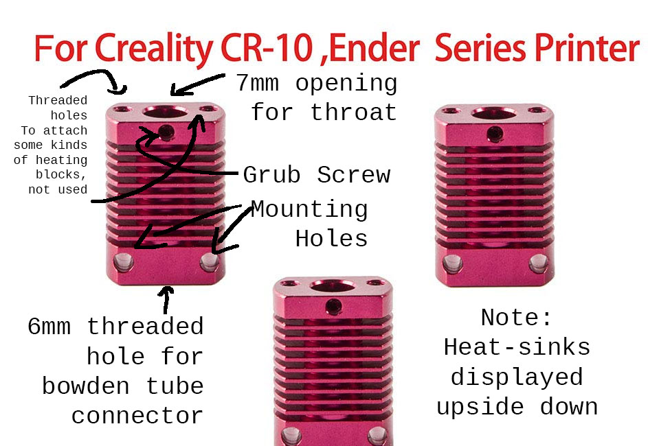
Above you see a diagram I made of the new heat-sinks out of a picture from amazon. They did not include any grub screws and they have a seven millimeter smooth hole in the bottom of them for the throats and a threaded six millimeter hole for the connector in the top. They are shown upside down though so I’m sorry for the confusion. They are to be mounted the other way in the machine. The original heat-break on the machine had a 6mm threaded hole all the way through and a PTFE lined throat.
This is the link to the new heat-breaks https://www.amazon.com/gp/product/B07PHDMWQ4/ref=ppx_yo_dt_b_asin_title_o07_s00?ie=UTF8&psc=1
Because the heat breaks didn’t include grub screws I needed these as well. https://www.amazon.com/gp/product/B077SRNQZB/ref=ppx_yo_dt_b_asin_title_o01_s00?ie=UTF8&psc=1
So apparently the old style throats are six millimeter along their whole length and they are threaded their entire length and the new ones are six millimeter at the end which screws into the heat-block but enlarge to seven millimeters along the rest of the shaft. They do it this way now to facilitate a better transfer of heat from the throat to the heat-break to help prevent “heat creep” up the throat which makes sense, but it caused compatibility issues with the older parts. But even more confusing is they no longer call them throats, but instead heat breaks. And to make matters even more confusing some are threaded along their shaft and some aren’t. I got the threaded kind even though the unthreaded is what my heatsinks called for, but that proved to be an asset as the threads provided grooves to smear thermal paste into, but there was a major problem with them. While I ordered new throats I was a little concerned as they appeared to be shorter than the original ones and once I tried them this proved to be a problem since the bowden tube can not go fully into them. This means retraction will always jam up the system because the bowden tube is flexible and will bend upon retraction. The bowden tube needs to go down into the heatbreak/throat so that it can not bend. This is what distinguishes a non-all-metal-hotend from an all-metal-hotend. If you have an all metal hot end you can use filament that requires a higher temperature than what PTFE starts to soften at, but you WILL have trouble with retraction and you to dramatically decrease the speed of retraction and ensure you have good cooling around your heatsink to prevent any creep towards the top of the assembly.
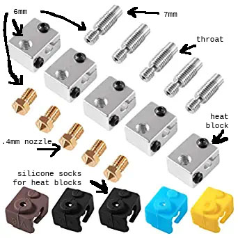
Above you see a diagram I made from a photo from amazon of the heatblocks, the throats, the nozzles/tips, and the insulating socks I bought. https://www.amazon.com/gp/product/B07K9HFFYC/ref=ppx_yo_dt_b_asin_title_o05_s00?ie=UTF8&psc=1
So the new throats are called “heat-breaks” and they are designed especially for cylindrical heat-sinks which are common on the hot-ends made today like we see on the Ender v6 All Metal Hot-Ends.
Here’s a link to Ender v6 type hot end, but a cheaper branded Gulfcoast Robotics. Notice how the connector doesn’t look like it has enough insider diameter for the bowden tube to go all the way through? That’s a PROBLEM, but it’s easily fixed by changing the throat to a full length kind that the bowden tube can go down into. https://www.amazon.com/Gulfcoast-Robotics-Hotend-Extruder-Printer/dp/B07B4FL12R/ref=sr_1_4?keywords=ender+v6&qid=1567106066&s=industrial&sr=1-4
I learned they make longer heat-breaks with no threaded 7mm tops apparently too though. I think these would be better than the threaded kind if your heatsink doesn’t have a threaded connection or if you have one of the bowden connectors that don’t allow the bowden tube to pass all the way down into the heat-sink to meet the heat-break. I ordered some it solved the problem entirely and retraction on the printer works flawlessly now. https://www.amazon.com/gp/product/B07MVVD99L/ref=ppx_yo_dt_b_asin_title_o04_s00?ie=UTF8&psc=1
So not only is there a problem with some of the heatbreaks not allowing the passage of the bowden tube down them, but also in the older style setup the bowden tube wouldn’t go down into the heat-sink very far. It would either be stopped by a smaller diameter shelf within the bowden tube connector (the connector is screwed into the top the heat-sink and is what holds the bowden tube in place) or it would be stopped when it hit the older style throats which were too long.
So in either case the bowden tube wouldn’t go very far into the heat-sink. If the filament passed any distance while not being in a bowden tube or throat it was near the top of the heat-sink where there isn’t much heat so as long as the heat-sink and fan was working correctly there wasn’t usually a feeding problem, but in some cases when heat would creep up the system you might run into trouble. In those cases you would be able to feed the filament in, but once the filament retracted a bit because it was soft it wouldn’t feed back in and would curl near the top of the system and cause a blockage. That was happening with my printer A LOT after trying to switch things around but hadn’t happened when I used the hot end setup it came pre-installed with. The chinese setup worked, but it was hard to replicate because the parts weren’t readily available.
The retraction failure will surely happen if you use the newer system with the shorter throat/heat-break if the bowden connector you have is of an older kind with a shelf inside which does not allow the bowden tube to pass all the way down to meet the heat-break. This is precisely what happened in my case. So I had to replace the bowden connector also.
I used these. The white metal ones allow the bowden tube to go all the way through and down into the heat-block/throat. Yay! And they included three bowden tubes. Yay! And brass threaded connectors that you can thread into the tubes if I want to use the bowden tubes for a watering system someday. Yay? I guess that’s cool, it’s just that a watering system wasn’t what I was making, but I might someday so YAY! https://www.amazon.com/gp/product/B07NXQT75Y/ref=ppx_yo_dt_b_asin_title_o03_s01?ie=UTF8&psc=1
Now with the new heat-sinks, the new bowden connector, and the new throats/heat-breaks, I suspected the system would work correctly but I didn’t install it for a while since I repaired my old system in the mean time.
I found out the new system STILL DOESN’T work. I’ll explain why but first I noticed a few other issues which you may encounter:
The opening of the heat-breaks which receive the bowden tubes are a bit oversized in some people’s which means the bowden tube can too easily be retracted. This isn’t much a problem since the bowden connector is what holds it in place, but some people have complained that their connector didn’t hold the bowden tube tightly or else actually pulled it out a bit when the button which opens it up to allow the bowden tube to pass through it was un-depressed.
Mine are very tight, but if yours are loose perhaps pressing the tube in hard while un-depressing the connector may solve the problem or replacing the connector may fix this, but I suspect at least some people like me didn’t at first notice that their bowden connectors had a shelf in them so that the bowden tube can’t go all the way down inside the heat-sink preventing it from being inserted into the end of heat-break.
Either way if the problem is that the bowden tube is retracting a bit leaving a gap between it and the heat-break the same blockage will occur as I described, but near the bottom of the heat-sink instead of the top.
By inserting something like a very dull pencil into the end of the bowden tube after it has been allowed to pass through the bowden connector and twisting the pencil using the heat of the friction to flare out the end of the tube so that it fits more tightly inside the end of the heat-break may help.
If all else fails a 3d printed part may work for you. A man designed a collet with a tightening nut to replace the bowden connector which should hold the bowden tube in place extremely well, but it should be printed from higher temperature plastic like PETG or ABS so that it does not soften in cases of heat-creep. I’ve provided the link to the invention here.
Explanation Video https://www.youtube.com/watch?v=Fb4XMbZ0iA4 & The Actual Thing https://www.thingiverse.com/thing:3348742
I printed one and it looks like it would work well, but I’ve replaced my connector already with a new one that has a straight inside and it holds the tube very well so I suspect that the new system will work now.
I also noticed the new heat blocks are smaller than the ones I had so that my long heater sticks out a bit from the end of the new heat-block I bought. I don’t like this as that is wasted heat and having a protrusion of the heat-source from the heat-block increases the risk of a fire and injury. Others use it that way and don’t have a problem with it, but I don’t like it. So I replaced the heater as well with the shorter kind I got when ordered the new throats/heatblocks since the smaller blocks seem to be standard now and I could use the insultating socks the other parts came with.
Now here’s the actual problem: The new style heatbreaks are simply too short. They are so short that upon the first retraction the filament develops a bulge where the heatbreak and bowden tube meet. Even if the bowden tube is tightly held in place this occurs. The reason is that the bowden tube is flexible so bends just a bit regardless when backward pressure is applied. The only solution is a longer heatbreak. It should be as long as possible. If you still have an old heatsink just use the old style throats as they work perfectly. If you have a volcano type tip you also should be fine as those have a single piece for the throat and tip.
But if you have the new short heat breaks you might be able to get away with using them IF you insert them fully in the heatsink and you have a lot of cooling from the fans directed at the heatsink. Having a sock on the hotend will help, but it won’t stop the problem by itself. Slowing down the retraction speed and distance can also help, but honestly not much. The ideal solution would be to just get an old style heatsink with those old 6mm holes if you can find any and old style 6mm throats. That’s what I used temporarily with the new style block with a sock on the block and it was working great. I tried the new style heatbreaks with the new style heatsink and it just didn’t work no matter what I tried. Like I wrote if you have a lot of cooling on the heatsink it might, and if you use thermal paste you’ll get much better cooling, but honestly I don’t think it’s worth it to try to make the short heatbreaks which don’t allow the bowden tube to pass all the way through them to work. The old system of 6mm throats worked fine and I wish somebody still made the old style 6mm heatsinks. But the kind of heatbreaks 7mm heatbreaks that allow the bowden tube to pass all the way through them https://www.amazon.com/gp/product/B07MVVD99L should work fine as long as the bowden tube is tightly secured. That’s what I’ve got on their now and everything is working perfectly.
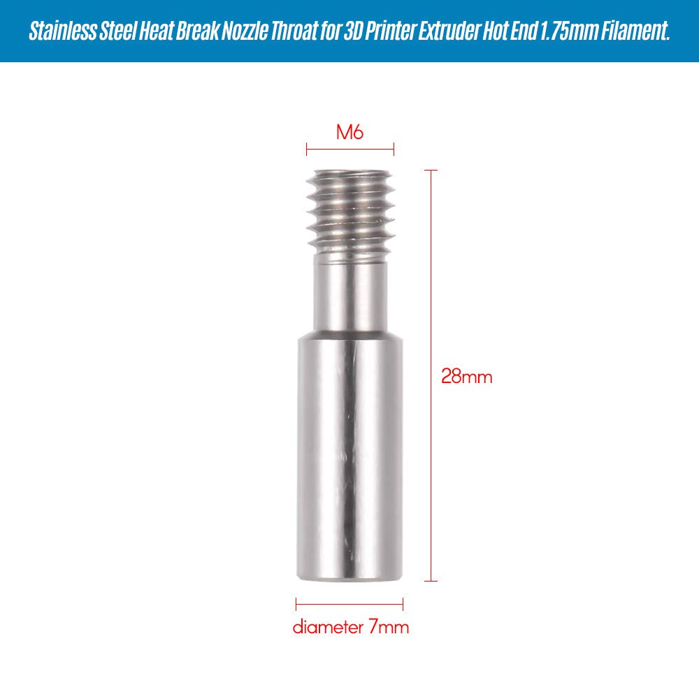 Long Style heatbreak/throat. It’s upside down but the bowden tube can go deep inside the 7mm top so that the tube provides self lubricating PTFE guidance of the filament all the way down to the 6mm nozzle and facilitates easy retraction too without jamming which is super important. This is the correct and superior design to use. It actually works. The outside of the shaft is not threaded. That’s fine. As long as your heat-sink doesn’t require it you don’t need threads as the grub screw holds this style of heat-break/throat in place just fine.
As a temporary fix as I was working to create a whole new hot end I fixed my old heatsink by simply forcing a slightly larger screw into the stripped screw hole. I used the kind of screw used for computer cases. It was tight, but not too tight and it cut new threads that worked. It’s actually better than the grub screw. The first two screws I tried weren’t quite large enough and didn’t hold, but the third did and so I was able to reassemble my old system and it worked quite well. Apparently the stripped grub-screw wasn’t holding the throat very well before and that was making it very hard to tram the bed to what had become a shaky hot end for a number of reasons.
Now another problem I was having is that the side fan which cools the parts down had a broken shroud. They used a cheap 3d printed part that was made with a layer height too high so it broke at the layer just below where the screw hole was which has the most stress. Very predictable problem by anybody who has designed 3d parts so it’s hard to understand why they’d do that, but I had to print a new shroud and I’m trying a few designs. The one I currently tried doesn’t have enough clearance for the heat-block and sits too low on the thing I’m printing and will scrape it a bit so I’m going to try a few designs until I find the one I can recommend or I’ll make one myself. But that’s not the worst part.
The problem is that side fan/parts fan stopped working. It’s a 40mm x 40mm x 10mm thick downward blowing fan 12 volt. So I ordered a new one. They come in a set of two so I have a backup now so that’s cool, but I did learn that the parts fan doesn’t spin when only a very low voltage is put through it so needs to be set at about 50% or 60% before it will start spinning on it’s own. At lower setting you can sometimes get it started by spinning it with your finger, but sometimes not, so if you want the fan set at something lower than maybe 60% I suggest editing the gcode to start the fan at 60% or 70% and then back it down once it starts spinning and it is more likely to keep spinning at the lower voltage due to momentum and because it has already overcome the initial problem of friction. Bodies at rest and all that right? https://www.amazon.com/gp/product/B07RNZF97F/ref=ppx_yo_dt_b_asin_title_o02_s00?ie=UTF8&psc=1
After I pulled the old fan I noticed that what had happened is that the solder point for one of the wires had broken. I figure just from taking the unit apart a couple of times the wire gets pulled and eventually the connection breaks. I could have resoldered it and seen if that would have fixed it, but I didn’t like how easily it broke so I opted for improving the machine.
So I went ahead and ripped the other wire off at the other solder point and stripped back the original wires a bit. There wasn’t a lot of wire left since they kept their wires short when doing the assembly but there was enough to work with if I was careful.
The wires are so thin my strippers didn’t work well and I had to be careful.
I considered attaching a connector and had one coming since I ordered a different fan for another thing which I’ll get to, but I decided not to wait for my order to come in and I just cut off the connector from the new fan and I twisted and soldered the connections.
Before I did that I placed heat shrink on both wires and then on each set of wires individually to tie them together for good cable management and to protect the wires from getting pinched when reassembling the hot end. I soldered them together and then I used a heat gun to shrink the heat shrink. It’s great now. I doubt the connection will break again.
I used this heat shrink (a great kit): https://www.amazon.com/gp/product/B072PCQ2LW/ref=ppx_yo_dt_b_asin_title_o02_s00?ie=UTF8&psc=1
One wire is black with a bit of red and the other is just red. The darker wire is the negative end and the red is the positive: Not that it matters. I just put the same colored wires back together, red to red, black to black, and it was fixed.
One note about soldering: I first used a butane soldering gun which I have and which I prefer, but that ran out of butane so I grabbed my old plug-in iron which I hate using since the whole thing gets hot, but it works reliably. It’s just that it takes forever to cool down. And that leads me to a VERY important safety tip:
When soldering you should have a fan going not just to remove the fumes, but also to cool down your iron after you are down with EACH WIRE if you haven’t prepared the wires correctly so that you can both wires at the same time.
Do NOT lay down the iron to prepare the next wire for soldering. Prepare both ahead of time and never under any circumstances try to do anything other than solder when the soldering iron is hot. That’s critical.
Never mess with the wires while the iron is hot and never EVER lay down a soldering iron. Even if your table is magically fire proof AND IT IS NOT the soldering iron WILL roll off your table or be pulled off your table by something pulling on the plug or be knocked off the table onto your floor by you or someone else and it WILL catch your house on fire. And make certain that you also have a cup of water and a fire extinguisher at arms length just in case that happens!
If your other wire is not prepared properly for some reason do one wire only then shut off and unplug your iron and HOLD IT in front of the fan for about ten minutes checking the temperature by touching first the lower part of the shaft and if that’s still warm AT ALL the tip is still blistering hot. Once you feel the shaft is cool check higher and higher. If at any time you feel warmth the thing is not cool. The tip is still blistering hot. Do not lay it down. Do not do anything except cool the iron with the fan. Keep it in front of the fan!
When finally the tip itself is perfectly room temperature you can lay it down and get things ready to do the second wire.
Obviously if you prepare both wires correctly you may not have to cool the iron down after doing the first one but some things happen; like maybe the ends come loose from the second set of wires while you are soldering the first. Stuff happens.
But as long as you don’t try to redo those wires while the iron is hot in your hands and as long as you don’t lay it down until it is entirely at room temperature you’ll be safe.
I recommend using solder with rosin in it. It’s worth the extra cost. Soldering flux and soldering pens are very useful especially when you need solder to move around something or to move solder uphill, but in a hurry the rosin core stuff works really well.
Another problem with my Anet I noticed is that one of the fans inside the control box is making a lot of noise. It’s the same size as the other at 40 x 40 x 10 mm, but of a regular fan type instead of a blower style. I ordered a new one, a rather expensive one, but the brand has a reputation for being super quiet and it includes special connectors that I want to use.
The fan inside the controller box that is causing problems is not the one near the vent and not the one in the power supply. It’s the one near the front of the system that just helps circulate air throughout. It’s wired directly to the power supply so it shouldn’t be hard to replace, but I’ll be using the connector so I can replace the fan more easily in the future if it ever goes out. This is the one I ordered. https://www.amazon.com/gp/product/B009NQLT0M/ref=ppx_yo_dt_b_asin_title_o00_s00?ie=UTF8&psc=1
I did notice on the old fan that removing the Anet brand sticker helped the center spin more freely and that cut down on the noise a little, but still replaced it since I didn’t want it going out when I didn’t have time to replace it. It
The anet uses round wheels and the one near the front of the print head is loose causing some wobbling so I at first tried replacing them with these wheels but the new wheels were too large in diameter (my research leads me to believe the correct sized wheels are a bit odd for this machine) and made of a hard plastic instead of rubber, but it doesn’t matter as the solution was something else as I’ll cover in the next paragraph. It wasn’t actually a problem with the wheels, it was a problem with the spacers/nuts.
These were the wheels that I got that were too big: https://www.amazon.com/gp/product/B07KXPD6XZ/ref=ppx_yo_dt_b_asin_title_o00_s00?ie=UTF8&psc=1
Now what I’ve read is that the wheels for 3d printers are classified as big wheels and small wheels. The big wheels measure outside diameter 24mm with a hole diameter of 5mm and a height or thickness of 10.2mm. The small wheels are 15.3mm outside diameter, 5mm diameter hole, and 8.9mm height or thickness. I’m pretty sure the Anet E12 uses larger wheels, but as large as the ones I bought, but not as small as the 15.3mm. My research suggests the correct diameter for the Anet E12 wheels is 23.89mm with a thickness of 10.23mm which are here… https://www.amazon.com/BIQU-Plastic-Pulley-Bearing-Printer/dp/B01FJHZ42M
But it didn’t matter because I found the real problem which happened to be two problems both related to the spacers between the wheel and the carrier plate. But if you need to buy the smaller wheels or a 6mm or 8mm eccentric column/nut I have provided a link: https://www.amazon.com/Befenybay-Hexagonal-Eccentric-Column-Printer/dp/B08FR8B2BV/
The wobbly print carriage/print head is supposed to be easy to fix by loosening the wheel underneath, lifting it a bit and tightening it again. The hole in the mounting plate is oblong allowing you to do this. But it’s hard to adjust. You need three hands to do it well or you have to put something under the carriage to lift it a bit while doing it, but worse there is a serious design flaw on the Anet E12 as it is assembled from the factory. The nylon plastic spacer/cylindrical column/round column/pillar or (whatever they decide to call these parts today) for the two wheels above are simple cylindrical spacers but the one below is oval shaped on one end and fills the oblong shape in the mounting plate. That sounds fine, but it fits perfectly allowing no play so the wheel on the underside of the print head that you are supposed to be able to lift to tighten the print head so that it doesn’t wobble can’t actually be lifted. Chinese ingenuity I guess.
I figure that the spacer was designed for a plate with a longer oblong hole in which case it would work fine, but it fits perfectly so can’t be moved. You could try to fix this by flipping the spacer around so that it doesn’t matter or you could replace the nylon spacer with a regular one like those two above the print head or you could do what I did as a temporary fix and use two metal nuts that make up the same height when stacked together and use them instead of the nylon spacer.
I found this worked really well as a mickey mouse fix and made it much easier to loosen and tighten the wheel for I could remove the regular disassembly nut and remove the wheel and lift the bolt to the correct height, tighten the first nut I used to replace the spacer a bit leaving a little slack, then the second one I used to replace the spacer and then replace the wheel and disassembly nut and everything went together well.
You might have to loosen the wheel above to give yourself a little play to get the wheel back on below, but this is what worked for me.
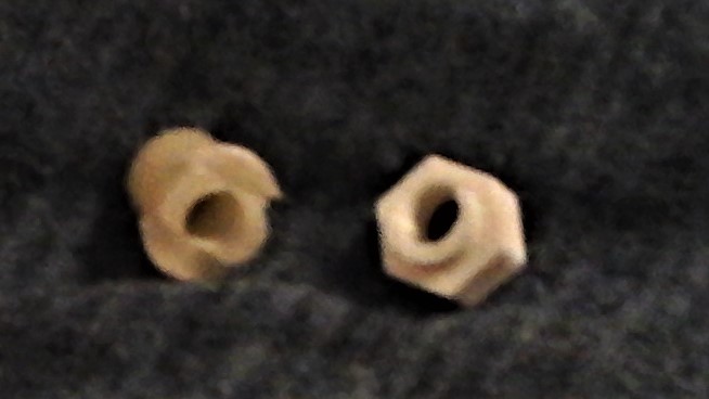
After I got the machine working again I printed some eccentric nuts out of PETG and replaced the temporary metal nuts with one proper PETG plastic eccentric nut which worked perfectly for rotating a eccentric nut, because the hole is offset, tightens the wheel. They sell metal eccentric nuts, but I saved about ten dollars by printing my own part in this case and I have lots of spares and can make more. The .stl file I used was from https://www.thingiverse.com/thing:2630026 and it worked perfectly. Below you can see the difference between the spacer that came on the machine which had an oblong shape at the end and the proper type eccentric nut/spacer that I was able to print out to replace it. Such a small part and yet the whole printer was suffering a major quality issue because of it. Stupid Chinese factory.
Now the problem was while the bottom wheel was tight the front top one was not. I tried tightening it and it just wouldn’t get tight enough. I think this may have been partly because the replacement spacer for the bottom wheel I made was a slightly different length than the one I had replaced making the length of the spacers on the machine all a bit different canting the carriage just a bit outward away from the frame of the machine near the front of the carriage so that the front nut would have to be a bit shorter than the original spacer that I still had on there.
So I temporarily replaced that nylon spacer (the proper term for this part is bearing wheel spacer bushing and a replacement can be found here but I made one myself later on… https://www.thingiverse.com/thing:3990239) with an orange eccentric nut that I had printed previously and that made the front end way too tight, so tight I couldn’t move the carriage at all, but that at least told me I was on the right track of finding a good way to get the whole printing head tight again.
So to falsely lengthen the eccentric nut I had printed I added a round paper spacer and now the front end was too loose again so I then modified the orange eccentric nut shortening it just a tad bit by running it over a fingernail file a couple of times and reassembled everything again combining the shortened orange eccentric nut with the paper spacer and it was just right. Later I printed a part that was the correct length I needed.
You can see in the photo below that the carrier plate didn’t sit perfectly parallel to the rail anymore but that doesn’t actually matter all that much. It’s wasn’t ideal, because it puts a little more tension on the belt on the front end than on the back, but it’s was fine for now and gave me a chance to print out some parts of the right length.
![]() Now I could print a more perfect replacement for the nylon spacer out of PETG or PLA that would be the right size without modifying the original nylon spacer which by this time I was certain was just a bit too long to make it possible to tighten the front end.
Now I could print a more perfect replacement for the nylon spacer out of PETG or PLA that would be the right size without modifying the original nylon spacer which by this time I was certain was just a bit too long to make it possible to tighten the front end.
This informs me that I should never have to bend the metal plate carrier if it is a little tweaked, but should instead adjust the length of the nylon spacers to account for that.
So I did model some replacements of both spacers and nuts. They were modeled for 10.55mm in length which is right for an eccentric nut, but a little short for a regular wheel spacer apparently but I can adjust the printing height of them in my slicer to make them maybe a few hundreds of an inch longer so I can file them to whatever length gives me the right tension on the front end.
I measured the spacer that I pulled off that was too long and surprisingly it was shorter than standard. The standard is 11mm for long ones and about 10 or 10.50 +- .05 for shorter ones, but the one I pulled off was .389 inches thick which is 9.8806mm.
The oblong spacer I pulled off also measures 0.389 inches thick even though it was a bit smooshed on the end so I presume all the spacers are supposed to measure an even 10mm in an ideal setup, but because the wheels are smaller around than standard they probably used slightly shorter ones to snug up the wheels better, it just wasn’t enough of an adjustment, especially not after I replaced the bottom left hand one with an eccentric nut making the front one terribly long in comparison. This may be why some of the screws that go through the carrier plate were a bit long. If the spacers are a bit short the carrier will be closer to the rails and the end of the screws that are threaded into the carrier might protrude from the back of the carrier rubbing against the rail. This was happening on my machine and I had to use little paper spacers on the screw against the head on the close side of the carrier to make up the difference. The screws could have been filed down, but that’s not a fun job.
The set of miscellaneous spacers and nuts I modeled prints them at 10.55 which is pretty close to what is needed and could be trimmed even shorter if necessary. Also if your bed is a little too high the first few layers will be really smooshed so it’s a good practice to make fine parts like these a little taller than necessary and only trim them to length by filing if necessary.
Side note: A standard leveling column for a 3d printer is made from silicone and is 18mm in height and 16mm in diameter but the way. The timing pulleys anet uses are either 16 or 20 teeth with 5mm hole, 13mm outside diameter, the teeth have a 9.5 mm outside diameter and the height is 15mm. https://shop.anet3d.com/collections/3d-printer-parts-and-accessories/products/5pcs-16-20-teeth-timing-pulley-for-3d-printer-prusa-i3?variant=33553698586761
The models I created for centric and eccentric nuts/spacers are here…
http://www.embscomputerart.com/stls/embs3dprinterwheelspacers&nuts.stl
While doing all this I also replaced the shallow headed bolts with deeply recessed hex bolts which are much stronger and won’t strip out. They are slightly shorter so it would be good to get longer ones, but they worked.
I’ll do the same replacing the bolts for the X-belt tension control as one of the heads is stripped out already and really hard to remove.
Also I am replacing the belt tension control with a printed part which will make adjusting the tension much easier. The original model is on thingiverse.com but I’ve already redesigned much of it. The original is here: https://www.thingiverse.com/thing:2482051
Eventually I’ll also replace the tension control for the Y-belt, but that’s less critical to me, but I will use the strengthening device that goes under the heat-bed which was recommended in the video of the part in the paragraph above. I would recommend making that part out of PETG or ABS if you use that since it will get hot.
Now I also had trouble with the limiter switch for the x movement of the printer. Sometimes the carrier plate would hit it correctly and sometimes it wouldn’t. This can be improved by tightening the carrier making it straighter if it was loose from the factory, but if that looseness had forced them to position the switch a bit strangely the switch might be way off when you tighten the carrier.
A common solution is to add a little plastic thing to the end of the metal switch lever to make it a bit bigger. Yeah that works, but that plastic piece is a pretty small part to print correctly and it can shift.
Another solution is you can bend the metal lever a bit up and down a bit which is a good solution to adjust for things like bed height, but you can’t really bend it side to side very well because it’s flat.
So the best solution is to move the switch to in line with the carrier so that the carrier can never miss it. But to do that I needed to make a new mount. I tried a few different designs other people had made until I came up with one of my own.
Using the switch holder I made I could now mount the switch sandwiched between the outside side of the mount and the rail of the printer. I just needed a way to mount the switch to the mount. Other designs I’ve seen like this used plastic cylinders to fill the two screw holes and hold the switch in place kind-of-sorta, but that doesn’t really work as they break. They are just too thin, but using screws works well.
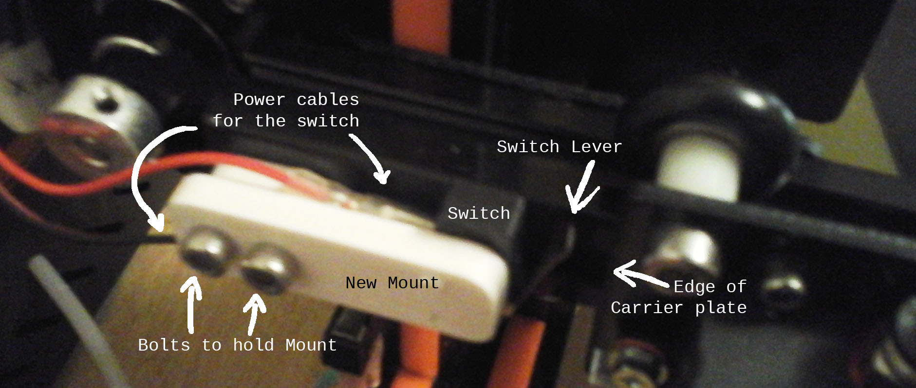
I just started the holes with a very small drill bit smaller in diameter than the screws I had and then the screws I had self tapped the rest of the way holding the switch in place. You could use a sewing needle held by pliers heated by a candle to melt a small hole for the same effect as using a drill bit. the same side of the switch holder as the raised area on the side of it between the outside flat part sandwiching it between the outside side and the rail of the printer and using some thin screws I could tap right into the plastic. You can’t see the screws because the heads are flush sitting against the railing on the far side of the switch, but they run through the holes in the switch and into the white plastic. There are two so the switch can’t rotate. There’s just enough room to get around the inside nodule on the mount (which acts as a spacer being the same thickness as the switch) to plug the power cables into the switch. I could have made the nodule larger and bored holes through it for the cables, but this worked out okay.
The whole switch mount can now be mounted to the printer with t-shaped rail nuts and bolts as you see in the picture below. The stl file for the mount is provided below that.
http://www.embscomputerart.com/stls/embsmountswitch.stl
Now my printer was singing. It needed some tender care to get it to this point, but it’s happy now. A cheap chinese printer that came with a few poorly chosen parts and that had some less than ideal assembly and that had some poor design mixed in created quite a few problems out of the box but was easily fixed by a genius white man who had never used a 3d printer before and had no idea how these machines are supposed to work.
Remember that mechanical intelligence is a particularly strong trait of Germans, but of the white race in general so you’ll often find people with German blood working on machines either repairing them or improving them or else designing new ones altogether. It’s our intelligence and labour that holds the world up. Never forget that and don’t take it for granted. Men, especially white men can walk away from it all because they aren’t treated well and are doing that very thing and society is crumbling because of it. Every machine requires a lot of thought and maintenance to make and keep running. Our society does not thank men enough, and especially not white men enough, for the critical role they play in making modern life possible. And communist countries like China and America exploit their workers to an extreme degree. It’s no wonder then that machines that come from those countries have design and quality control issues that have to be addressed by customers. Because of all the issues I had with the AnetE12 printer I couldn’t recommend it to someone unless they had mechanical skills because while I can diagnose and fix problems as I encounter them most other people can’t. But because I can I often save money buying cheaper products and working on them later. I’ve found you don’t necessarily get a well-working product from paying a lot more all the time either; it’s just more likely that you will. So for a starter printer I think the AnetE12 isn’t a good choice, but it saved me a lot of money as most large format printers are very expensive so for that I am thankful. So also keep in mind that just because a machine is giving you some trouble doesn’t mean you should give up on it. It might turn into a great performer in the hands of the right mechanic.